This site intends to present technical proposals on hydraulic steel structures such as hydraulic gates,
intake and discharge equipments, silt/sand dischargers etc. which are provided harbour entrances, docks
and locks along waterways, or dams, weirs, floodgates and power stations on rivers, or irrigation systems.
|
|
|
|
PROPOSAL1 【STORM GATE・・TORSION TYPE】
|
Mitigation of Warping & Optimum Design
|
|
Contents
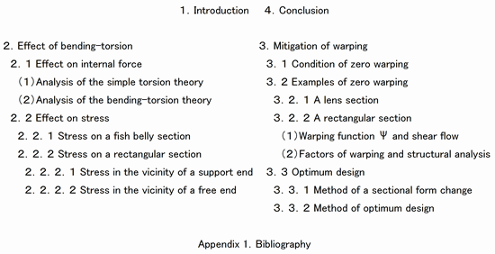
1.Introduction
A torsion type closed thin shell section is overwhelmingly superior in structural functions to a bending type structure because the torsion type resists against external load with second power of the closed area whereas the bending type resists with moment of inertia of thin shell, and this superiority gets more remarkable as the structural span becomes longer.
Simple torsion and bending-torsion yield in a torsion type structure of storm gate. Shearing stress of simple torsion distributes uniformly over the section whereas stress of bending-torsion meanders. Loads on the structure are carried mainly by the simple torsion, but maximum shearing stress on the section eminently increases with existence of the bending-torsion. In addition, vertical stress which is in equilibrium with the shearing stress of bending-torsion exists on the section. The vertical stress has a causal relationship with a sectional warping.
The vertical and shearing stresses of bending-torsion will decrease with a warping reduction operation. But the warping operation will result in section modulus decrease and deformation increase which may cancel effect on stress of the warping operation.
The most important section modulus controlling deformation of a torsion type structure is Jt. Although Jt decreased because of the warping operation, a gate weight cut is possible by making up the lost Jt with help of a cross section form change.
Superiority of the torsion type structure to the bending type can become more clear with application of optimum design which includes the warping operation and the form change and whose object function is cost.
�
2.Effect of bending-torsion
2.1 Effect on internal force
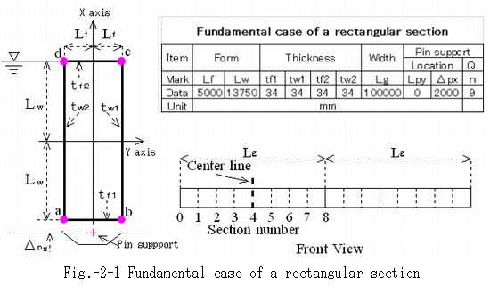
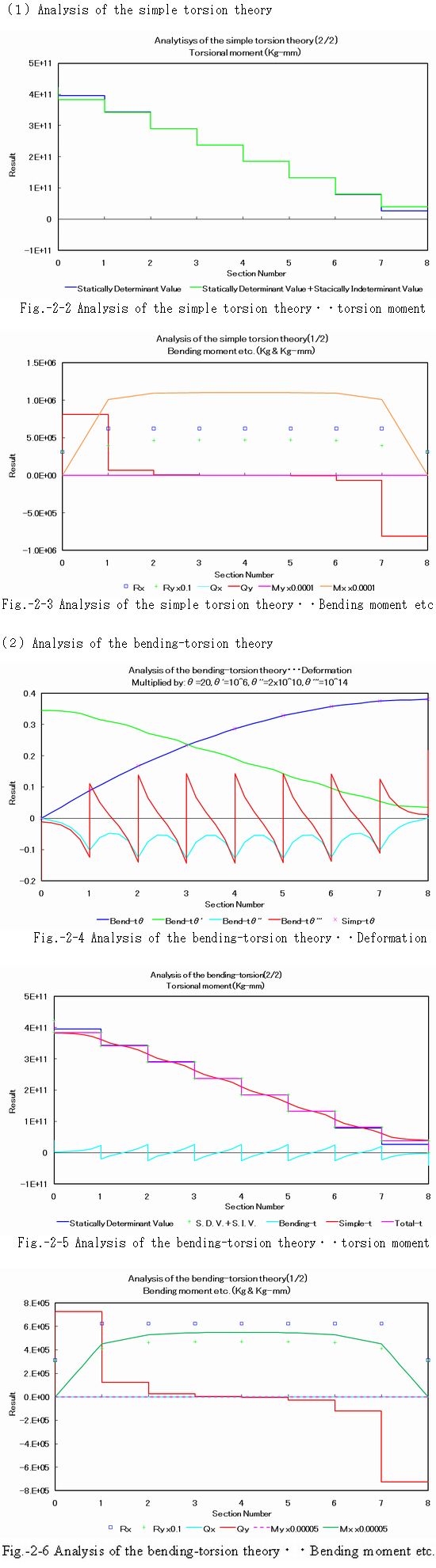
Fig.-2-1 is Fundamental case of a rectangular section, on which it will be shown that no big change due to the bending-torsion occurs in internal forces. 0 of the front view in the figure is a support end and 8 is a free end.
|
|
|
|
Fig.-2-2 and Fig.-2-3 are internal force analyzed by the simple torsion theory and Fig.-2-4 thru Fig.-2-6 are internal force and deformation analyzed by the bending-torsion theory. Deformation of the simple torsion theory is shown in Fig.-2-4 of the bending-torsion theory. My which is bending moment around Y axis and Qx which is shearing force in X direction are zero because the pin support in Fig.-2-1 locates on X axis on which shearing center is also.
Change in cross sectional internal forces due to additional bending-torsion is as follows.
(1) Internal torsion moment has a small difference, but no change at support terminal.
(2) Sum of simple and bending torsion moments is equal to internal torsion moment.
(3) Small decreases in bending moment and shearing force on the section.
(4) Twisting angle has small decrease, but no change at free terminal.
|
|
|
|
2.2 Effect on stress
It is shown on two sectional forms, a fish belly section and a rectangular section, that the shearing stress which distributes uniformly over a section of the simple torsion will meanders due to addition of bending-torsion moment and its peak value increase to a remarkable extent. The section whose stress is shown is identified by, for example, 1out or 1in where 1 indicates section number and out or in indicates outside or inside of the section with respect to a center line of gate. Stresses of both side of a section are presented because their distribution are completely deferent since sign of bending-torsion moment turns over at the section. The section number and the center line are shown on a corresponding figure.
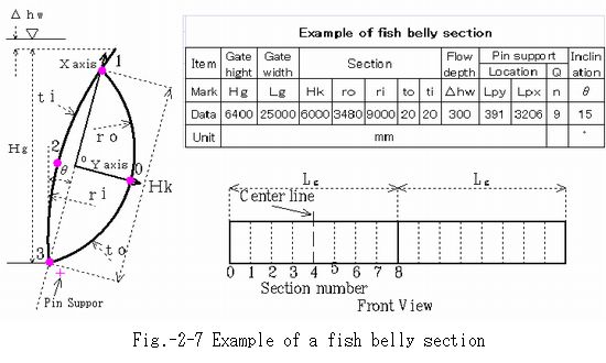
2.2.1 Stress on a fish belly section
A fish belly section is often applied to flap gates of reservoirs or rivers. Fig.-3-7 shows its example. Section Number 0 on the figure is a support end and that of 8 is a free end.
|
|
|
|
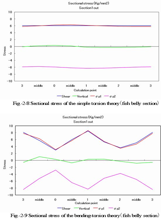
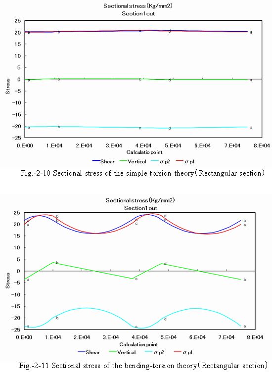
Fig.-2-8 shows sectional stress of the simple torsion theory and Fig.-2-9 shows that of the bending-torsion theory. Lateral axis on the graphs is girth length along the section shown on Fig.-2-7 and the numbers 0, 1, 2 and 3 on the axis correspond to pink colored points on Fig.-3-7.
Explanation of Fig.-2-8 (simple torsion): Shear is abbreviation of shearing stress which corresponds to the sum of simple torsion stress and shearing stress relating to bending. Vertical is abbreviation of vertical stress which corresponds the sum of stresses by bending moments around X and Y axes. σp1 and σp2 are principal stresses calculated from the shearing stress and the vertical stress. Stress status of the section is almost in pure shearing because absolute value of σp1 and σp2 is almost equal to the shearing stress.
Explanation of Fig.-2-9 (bending-torsion): Shear is abbreviation of shearing stress which corresponds to the sum of simple torsion stress, bending-torsion stress and shearing stress relating to bending. Vertical is abbreviation of vertical stress which corresponds the sum of vertical stress by sectional warping and stresses by bending moments around X and Y axes. σp1 and σp2 are principal stresses calculated from the shearing stress and the vertical stress. Stress status of the section is almost in pure shearing because absolute value of σp1 and σp2 is almost equal to the shearing stress. Vertical stress by sectional warping corresponds to a majority part of total vertical stress but is not still dominant among sectional stresses. The more calculation points, the more smooth curves we will get in cases of the shearing stress and the principal stresses. The maximum shearing stress increase rate of bending-torsion versus simple torsion is about 33 %.
|
|
|
|
2.2.2 Stress on a rectangular section
A rectangular section has been applied to a flap gate of ultra-large ship repair docks. This sectional form is recommendable for a torsion type flood gate of our technical proposal. Two examples are presented for comparison. One shows stress on a section in the vicinity of a support end where applied twisting moment is big and other shows stress on a section in the vicinity of a free end where applied twisting moment is comparatively small.
2.2.2.1 Stress in the vicinity of a support end
Sectional stress in the vicinity of a support end of Fundamental case shown on Fig.-2-1 is presented. Applied twisting moment is maximum at a support end.
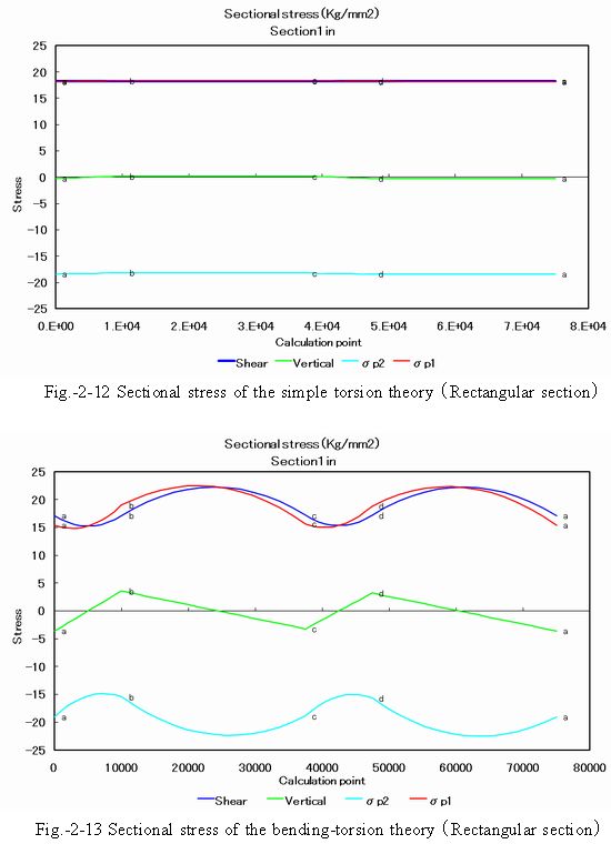
(1)Section 1out
Fig.-2-10 shows sectional stress of the simple torsion theory and Fig.-2-11 shows that of the bending-torsion theory. Lateral axis on the graphs is girth length along the section shown on Fig.-2-1 and the sign a, b, c and d in the graph correspond to pink colored points on Fig.-2-1.
Explanation of Fig.-2-10 (simple torsion): Shear is abbreviation of shearing stress which corresponds to the sum of simple torsion stress and shearing stress relating to bending. Vertical is abbreviation of vertical stress which corresponds the sum of stresses by bending moments around X and Y axes. σp1 and σp2 are principal stresses calculated from the shearing stress and the vertical stress. Stress status of the section is almost in pure shearing because absolute value of σp1 and σp2 is almost equal to the shearing stress.
Explanation of Fig.-2-11 (bending-torsion): Shear is abbreviation of shearing stress which corresponds to the sum of simple torsion stress, bending-torsion stress and shearing stress relating to bending. Vertical is abbreviation of vertical stress which corresponds the sum of vertical stress by sectional warping and stresses by bending moments around X and Y axes. σp1 and σp2 are principal stresses calculated from the shearing stress and the vertical stress. Stress status of the section is almost in pure shearing because absolute value of σp1 and σp2 is almost equal to the shearing stress. The warping stress which corresponds to a majority part of the vertical stress may affect sectional stress to certain extent but is not dominant. The maximum shearing stress increase rate of bending-torsion versus simple torsion is about 20 %. Increase of stress occurs between a and b (bottom plate) and c and d (top plate), and decrease occurs between b and c and d and a (side plates).
|
|
|
|
(2)Section 1in
Fig.-2-12 shows sectional stress of the simple torsion theory and Fig.-2-13 shows that of the bending-torsion theory. Lateral axis on the graphs is girth length along the section shown on Fig.-2-1 and the sign a, b, c and d in the graph correspond to pink colored points on Fig.-2-1.
Explanation of Fig.-2-12 (simple torsion): Shear is abbreviation of shearing stress which corresponds to the sum of simple torsion stress and shearing stress relating to bending. Vertical is abbreviation of vertical stress which corresponds the sum of stresses by bending moments around X and Y axes. σp1 and σp2 are principal stresses calculated from the shearing stress and the vertical stress. Stress status of the section is almost in pure shearing because absolute value of σp1 and σp2 is almost equal to the shearing stress.
Explanation of Fig.-2-13 (bending-torsion): Shear is abbreviation of shearing stress which corresponds to the sum of simple torsion stress, bending-torsion stress and shearing stress relating to bending. Vertical is abbreviation of vertical stress which corresponds the sum of vertical stress by sectional warping and stresses by bending moments around X and Y axes. σp1 and σp2 are principal stresses calculated from the shearing stress and the vertical stress. Stress status of the section is almost in pure shearing because absolute value of σp1 and σp2 is almost equal to the shearing stress. The warping stress which corresponds to a majority part of the vertical stress may affect sectional stress to certain extent but is not dominant. The maximum shearing stress increase rate of bending-torsion versus simple torsion is about 22 %. Increase of stress occurs between b and c and d and a (side plates), and decrease occurs between a and b (bottom plate) and c and d (top ).
|
|
|
|
2.2.2.2 Stress in the vicinity of a free end
Sectional stress in the vicinity of a free end of the case shown on Fig.-2-14 is presented. Applied twisting moment at a free end is comparatively small. The section number 0 in the figure is a support end and section number 10 is a free end.
|
|
|
|
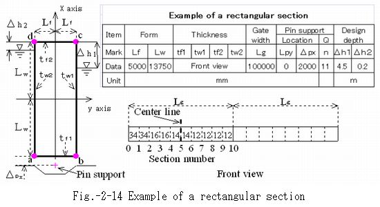
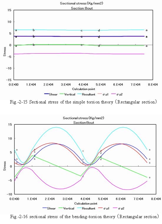
(1)Section 8out
Fig.-2-15 shows sectional stress of the simple torsion theory and Fig.-2-16 shows that of the bending-torsion theory. Lateral axis on the graphs is girth length along the section shown on Fig.-2-14 and the sign a, b, c and d in the graph correspond to pink colored points on Fig.-2-14.
Explanation of Fig.-2-15 (simple torsion): Shear is abbreviation of shearing stress which corresponds to the sum of simple torsion stress and shearing stress relating to bending. Vertical is abbreviation of vertical stress which corresponds the sum of stresses by to bending moments around X and Y axes. Resultant is abbreviation of resultant stress which is calculated according to the shearing strain energy theory (Mises-Hencky-Huber-Theory). σp1 and σp2 are principal stresses calculated from the shearing stress and the vertical stress. Stress status of the section is almost in pure shearing because absolute value of σp1 and σp2 is almost equal to the shearing stress.
Explanation of Fig.-2-16 (bending-torsion): Shear is abbreviation of shearing stress which corresponds to the sum of simple torsion stress, bending-torsion stress and shearing stress relating to bending. Vertical is abbreviation of vertical stress which corresponds the sum of vertical stress by sectional warping and stresses by to bending moments around X and Y axes. Resultant is abbreviation of resultant stress which is calculated according to the shearing strain energy theory (Mises-Hencky-Huber-Theory). σp1 and σp2 are principal stresses calculated from the shearing stress and the vertical stress. Stress status of the section is almost in pure shearing because absolute value of σp1 and σp2 is almost equal to the shearing stress. The warping stress which corresponds to a majority part of the vertical stress may affect sectional stress to certain extent but is not dominant. The maximum shearing stress increase rate of bending-torsion versus simple torsion is about 114 %. Increase of stress occurs between b and c and d and a (side plates), and decrease occurs between a and b (bottom plate) and c and d (top plate).
|
|
|
|
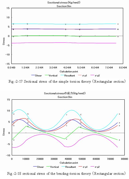
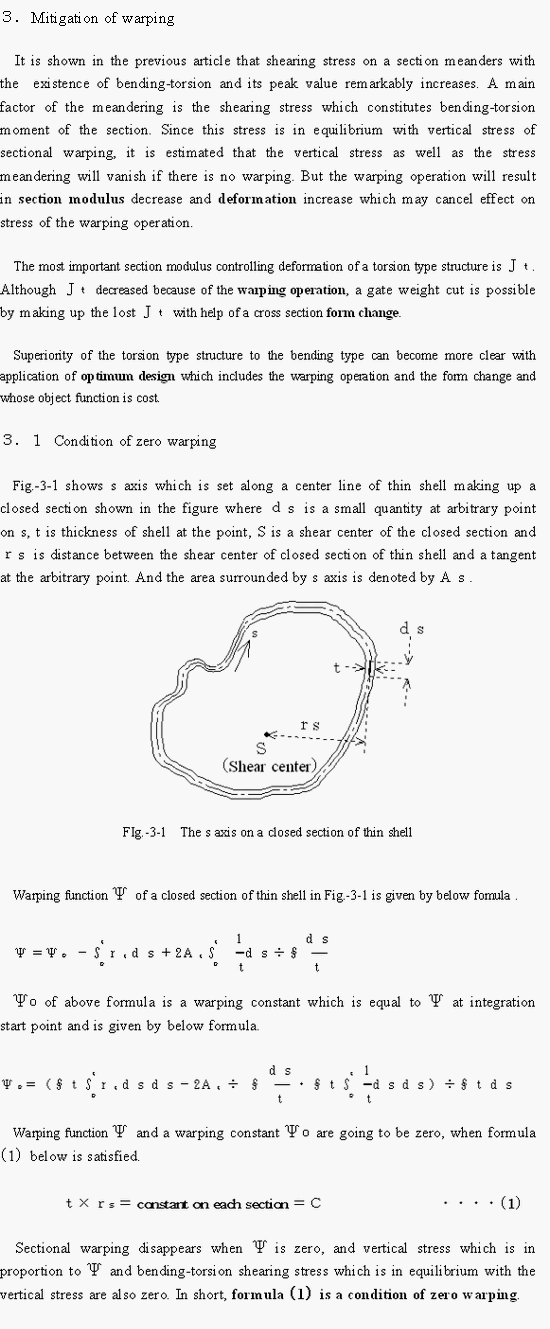
(2)Section 9in
Fig.-2-17 shows sectional stress of the simple torsion theory and Fig.-2-18 shows that of the bending-torsion theory. Lateral axis on the graphs is girth length along the section shown on Fig.-2-14 and the sign a, b, c and d in the graph correspond to pink colored points on Fig.-2-14.
Explanation of Fig.-2-17 (simple torsion): Shear is abbreviation of shearing stress which corresponds to the sum of simple torsion stress and shearing stress relating to bending. Vertical is abbreviation of vertical stress which corresponds the sum of stresses by bending moments around X and Y axes. Resultant is abbreviation of resultant stress which is calculated according to the shearing strain energy theory (Mises-Hencky-Huber-Theory). σp1 and σp2 are principal stresses calculated from the shearing stress and the vertical stress. Stress status of the section is almost in pure shearing because absolute value of σp1 and σp2 is almost equal to the shearing stress.
Explanation of Fig.-2-18 (bending-torsion): Shear is abbreviation of shearing stress which corresponds to the sum of simple torsion stress, bending-torsion stress and shearing stress relating to bending. Vertical is abbreviation of vertical stress which corresponds the sum of vertical stress by sectional warping and stresses by bending moments around X and Y axes. Resultant is abbreviation of resultant stress which is calculated according to the shearing strain energy theory (Mises-Hencky-Huber-Theory). σp1 and σp2 are principal stresses calculated from the shearing stress and the vertical stress. Stress status of the section is almost in pure shearing because absolute value of σp1 and σp2 is almost equal to the shearing stress. The warping stress which corresponds to a majority part of the vertical stress may affect sectional stress to certain extent but is not dominant. The maximum shearing stress increase rate of bending-torsion versus simple torsion is about 86 %. Increase of stress occurs between a and b (bottom plate) and c and d (top plate), and decrease occurs between b and c and d and a (side plates).
|
|
|
|
|
|
|
|
|
|
|
|
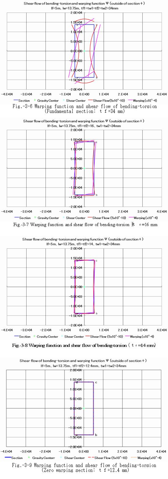
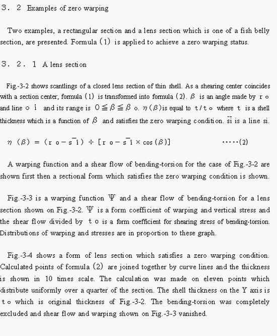
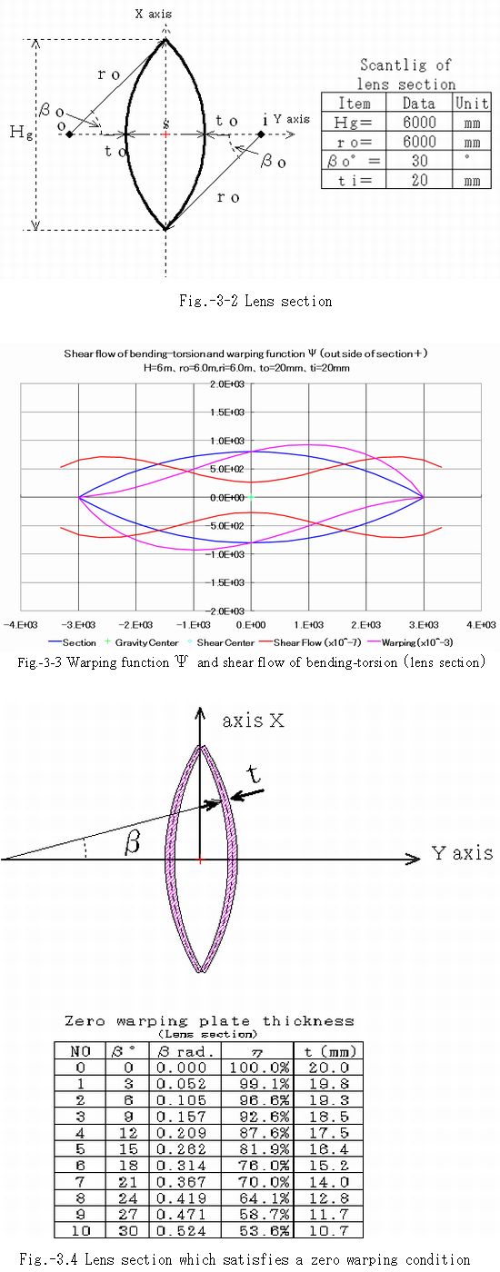
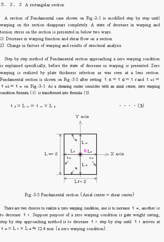
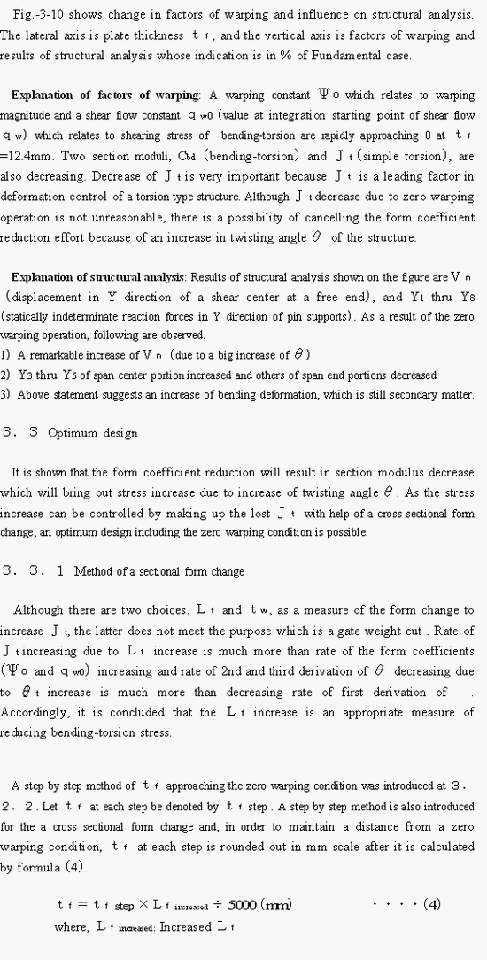
(1)Warping function Ψ and shear flow
Fig.-3-6 thru Fig.-3-9 show a state of decrease in warping function and shear flow. Fig.-3-6 is Fundamental section (tf=34 mm). Fig.-3-7 is a section of tf=16 mm, and Fig.-3-8 istf=14mm. Fig.-3-9 is a zero warping section (tf=12.4 mm).
|
|
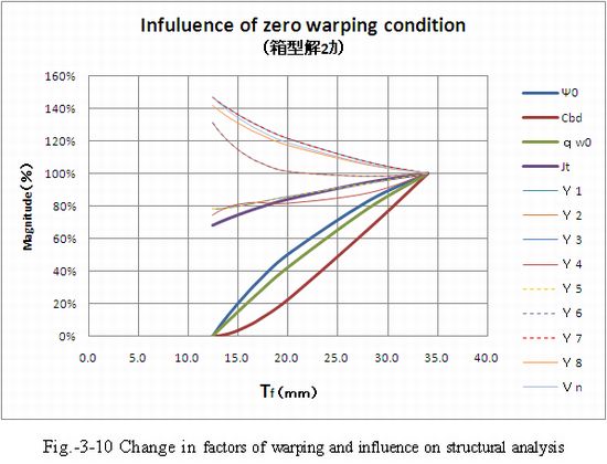
(2)Factors of warping and structural analysis
Purpose of this item is as follows.
1) To show quantitatively a status of decrease in sectional warping.
2) To show influence on the whole structure of the zero warping operation.
For a reference, the structural analysis was carried out according to the elastic equation method of bibliography (6).
Fig.-3-10 shows change in factors of warping and influence on structural analysis. The lateral axis is plate thickness tf, and the vertical axis is factors of warping and results of structural analysis whose indication is in % of Fundamental case.
|
|
|
|
|
|
3.3.2 Method of optimum design
Although purpose of a zero warping condition is gate weight reduction, that of optimum design is cost cut.
As cost composing factors include material, fabrication, transportation, site construction, maintenance, operation etc., minimum gate weight can not necessarily be minimum cost. For instance, there is an option that a high tensile steel plate of specially ordered thickness is fit in the shell of stress increased zone to keep minimum gate weight But it may be better idea in cost mind to increase gate weight in order to use ordinary strength steel plate of commercial thickness since cost of material and fabrication in the option is more expensive.
So far, stress which yields corresponding to whole structural deformation due to simple torsion, bending-torsion, warping, bending etc. is considered in the study, a torsion type structure which is planned according to a zero warping condition may not be a minimum weight after stress which yields corresponding to partial deformation such as bending due to applied hydraulic pressure on gate plates and their stiffeners, bending due to reaction forces of pin supports and support ends etc. is considered.
Suppose an actual conventional measure to find out an optimum design in cost is to select best one among multiple plans, an optimum design should be selected from not only a zero warping point but also a surface made by the two lines one of which is an approaching line to the zero point and other is a cross sectional form change line to make up the lost Jt.
|
|
4.Conclusion
(1)A torsion type closed thin shell section is overwhelmingly superior to a bending type structure.
(2) There are two types of structural torsion, the simple torsion and the bending-torsion.
(3) Sectional shearing stress distribution of simple torsion moment is almost uniform.
(4) The sectional shearing stress distribution meanders by additional bending-torsion moment.
(5) In some case, peak stress of additional bending-torsion is much more than 200% of simple torsion alone.
(6) Shearing stress of bending-torsion can be diminished by eliminating sectional warping.
(7) Jt will reduce due to warping reduction operation, and stress and deformation increase accordingly.
(8) Control of stress increase is possible by making up the lost Jtwith help of a cross sectional form change.
(9) An optimum design including the zero warping condition is possible.
|
|
Appendix 1.Bibliography
(1) H. Wagner、Verdrehung und Knickung von offenen Profilen、Festschrift. 25 Jahre T.H. Danzig、 S.329、1929
(2) H. Wagner, W. Pretscher、Verdrehung und Knickung von offenen Profilen、Lufo., Bd 11. Nr.6、1934
(3) Masatsugu Kuranishi、Elasticity、Kokusairikokenkyusha、1949
(4) Masatsugu Kuranishi、Applied elasticity、Kyoritsuzennsho、1957
(5) Toshie Okumura、Bending-torsion characteristics of a thin shell section、Recent topics in structural engineering、1967
(6) Hiroshi Terata、Structural analysis of torsion type gates、Journal of JSDE Vol.7 No.1 1997
(7) Hiroshi Terata、Studies on hydraulic gates、Dissertation、1996(submitted to University ofToyo)
|
|
|
|