�@�@This site intends to present technical proposals on hydraulic steel structures such as hydraulic gates,
�@intake and discharge equipments, silt/sand dischargers etc. which are provided harbour entrances, docks
�@and locks along waterways, or dams, weirs, floodgates and power stations on rivers, or irrigation systems.
|
|
|
|
�@
PROPOSAL�S�@�yDRAW-OFF GATE�E�EPILED UP SIPHON�z
|
�@
|
�@A technical proposal on draw-off gates of the piled up siphon for reservoir-use etc. is presented.
Details are as follows.
�P�DEstimation of Proposed Technology
�@The result of estimation on the top page is as follows.
�i�P�jThis technology is deemed to be satisfactory for a technical proposal. Its reasons are,
�@1) The initial cost is equal to or less than 1/3�`1/2 of the ordinary technology.
�@2) The operation and maintenance cost is equal to or less than 1/3�`1/2 of the
�@�@ ordinary technology.
�i�Q�jThere is no risk which prevents the proposal from being realized. Details are as below.
�@1) Fundamental subjects have been solved. (Fun. Sub.)
�@2) Development of Relating technologies has been completed. (Tec. Dev.)
�@3) Necessary prototype verification has been completed. (Pro. Ver.)
�@4) Interests of the beneficiaries coincide with the proposer's. (Bus. His.)
�i�R�jThe engineering level is �V (Short term verification).
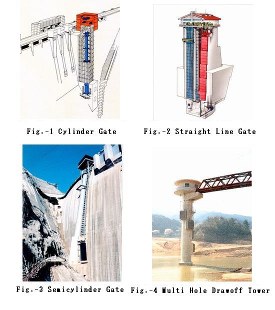
�Q�DImage of Draw-Off Gates for Reservoirs
�@Fig.-1 thru 4 show image of draw-off gates for reservoirs.
Various type of draw-off gates is provided in reservoirs to draw water from arbitrarily selected depth in the reservoir for the purpose of controlling outlet water quality.
The selective withdrawal from a specified water layer is possible with help of density gradient in reservoir water and its details are shown on the reference material 1 and 2.
Their necessity has more increased due to recent increase of social requirements against river running water quality.
The gates in Fig.-1 thru 3 are multi step type whereas Fig.-4 is called multi hole type
|
|
|
|
�R�DHow Did The Piled Up Siphon Come Out?
�@The antecedents of the piled up siphon is a siphon type draw-off tower which was invented in England early 60s last century.
U-shaped siphon pipes were embedded in the tower wall and the each siphon pipe was closed by filling the pipe top with air or opened by exhausting the air.
Its details are shown in the reference material 3 and 4.
�@The invention in England was innovatory because of being gate-less, but its construction cost was much more than ordinary technology because of electrode sensors to detect water surface height in the siphons.
The tower section became larger due to a dry chamber to install the sensors in it and decks, steps, an elevator, ventilators, lightening systems etc. were provided in the chamber for maintenance of the sensors.
�@The gate-less draw-off equipment of Haneji dam was realized as a result of a big cost-down due to adopting pressure sensors which were installed in the operation room and show air pressure in the siphons.
This new sensor arrangement is based upon a fact that the air pressure in a siphon corresponds to water head difference between a reservoir and the siphon.
Details are shown on the reference material 5 thru 7.
�@Although the draw-off equipment of Haneji dam has many merits in comparison with usual technology, it could not respond to the more wide needs of societies because it is multi hole type.
As a result of continual improvements, the piled up siphon emerged.
The difference of this from the Haneji type is that the floor plate of upper siphon is at the same time a top plate of the next siphon.
Consequently many steps of a siphon come to be arranged continuously and the concept of piled up siphon whose selective withdrawal function is at the same level as the multi step type draw-off gate was completed.
Fig.-5 thru 7 shows example of small, middle and large scale plan respectively.
|
|
|
|
|
|
4�DMerits of The Piled Up Siphon for Draw-off Gate
�@As the siphon withdrawal pipe is operated by air, there are many merits in comparison with a gate of movable steel structure.
�i�P�jCost is equal to or less than �P�^�R thru �P�^�Q of the ordinary one.
�@�@1) Construction cost:
�@�@�@�ESteel material is minimum thickness which is required for their fabrication.
�@�@�@�EAll siphons are of same scantlings and rough in their fabrication accuracy.
�@�@�@�EAn upper siphon floor is also a lower siphon top cover.
�@�@�@�ESmall screen area.
�@�@2) Operation and maintenance cost:
�@�@�@�EMechanical and electrical equipment is all installed in the operation room.
�@�@�@�ENo work at high position.
�@�@�@�ENo necessity of heavy weight handling.
�@�@�@�ENo necessity of underwater work (siphon pipes are maintenance-free).
�@�@�@�EAll mechanical equipment is multipurpose standard market goods.
�i�Q�jSeal function is perfect (air sealing, no wearing).
�i�R�jHigh reliability.
�@�@�@1) Sand and silt accumulation: Siphon can work in its own way.
�@�@�@2) Reservoir freezing: Low layer withdrawal is possible for surface freezing.
�@�@�@3) Driftwood piling: Low layer withdrawal is possible for surface close.
�@Fig.-8 indirectly shows that the initial cost of the piled up siphon is equal to or less than 1/3 thru 1/2 of the ordinary technology.
Steel weighs of the piled up siphon and the ordinary technology are plotted along the same axis.
The lateral axis is (a root of �p) x (withdrawal height).
�p is flow capacity of equipment.
The withdrawal height is difference in height between normal water level and lowest water level of a reservoir.
The product of both values is a variable which corresponds to equipment scale and has good correlation to equipment weight.
The longitudinal axis is the equipment weight.
The both axes are logarithmic.
The blue mark in the figure corresponds to the piled up siphon and the red one corresponds to the ordinary technology.
The ordinary technology includes different gate types whose weight are plotted with different red marks.
The weights of the ordinary technology are actual records whereas the piled up siphons are weights of preliminary designs.
Difference of the red group and the blue one is almost same value over the whole range.
The constant difference means that weight ratio of the both group is approximately constant over the whole range of equipment scale.
This ratio is approximately between 2 to 3 although there is small deviations among different gate types.
This suggests that a big and constant rate of cost reduction will be expected over the whole range of equipment scale including small to large ones.
For reference, the weight of the piled up siphon corresponds to a preliminary design specification which was established to keep construction cost minimum and there is a tendency of the weight increase at the detail design stages due to customer's requirements of a specification upgrade.
Although past cost increasing ratio is from a few to 55 %, the cost superiority of the piled up siphon does not change.
|
|
|
|
�T�DConstruction Records and Tax Payer Benefit
�@Fig.-1 shows a construction records of the draw-off gate of piled up siphon and tax payer benefit from the construction cost reduction due to adoping piled up siphon gates.
|
|
|
|
 �@
�@